As you can see, the SNR and the RSRQ are very low.
I do not know the cause and I yet don’t exactly understand how to troubleshoot SNR and RSRQ signal levels.
The maximum speed I get in Miami with 4 SIM’s is 40mbps down and 55mbps up with Speedfusion.
I currently have Vodafone UK cards in the USA and they have told me that the speeds could be throttled.
I think these signal levels are not good and I would like to know where I should be looking.
The yacht is steel, would this affect on the antennas?
Vodafone UK SIms in Miami will under perform compared to local in country SIMs. Often when roaming like this your internet traffic will get routed via the home country for accounting purposes, and if it does then you’ll take a bandwidth hit due to increased latency.
Looking at your numbers above I’d be interested to see the physical install of the Poynting antennas. Cellular 3’s high SINR suggests that it is in an area with a higher level of background RF noise.
Cellular 1 with its antennas up high away from the rest of the vessel has much better SINR on those same frequencies (Band 2).
Look at the B12 on Cellular 2 sitting there with SINR @ 13dB and a RSRQ @ -13dB thats interesting.
And the cellular 4 - is that antenna inside or just a lower gain antenna element I expect. Either way, the reduced reception of signal is working well on that module as less noise is being received so the SINR looks better.
I think you’re in an area with a high density of user equipment (smart phones / routers etc) likely a marina. The antenna at the top of the mast is more distant from those devices working at sea level and so is getting a cleaner signal. Cell 4 is either having its signal attenuated by the vessel itself (which is blocking a chunk of the crap noisy signal), or it just has lower gain antennas connected so less noise is being picked up.
I’d be tempted to force the other cellular modules to use B12 too and see what happens.
Do check what your public IP is on the VF UK SIms and then geoip lookup to confirm where that IP breaks out.
Also speedtest across all cellular modules individually and let us no the results for comparison, I suspect that you’ll find you get the best results using the mast head antennas and the internal Mimo because of the level of RF noise in your vicinity.
Thank you for your detailed explanation.
I understand the consequences of having a Roaming card, I have fusionhub running in the UK and the latency is of about 157ms.
The location of the antennas is just above the bridge. I thought it would be a good installation point as they are very close and there isn’t anything around them. They are separated by more than 3m. We are currently in dry dock so all navigation equipment is off and there should be no EMI or background noise that I can think of.
This antenna has a peak gain of 4dbi while the Poynting 402 have 6.2dbi
It isn’t a great deal of difference and there are placed at the same area. T
My rotational partner made the installation and bought LMR400 (good copy of Times Microwave) and N-type connectors from Amazon. He also made all the crimps without the proper tools. Hence the thought that it might be wiring.
I have ordered 4 Times Microwave SMA female to SMA male LMR240 from here:
I agree - this feels like a likely possible issue. Take that little panorama antenna and try in on the other three cellular modules and see what the difference in throughput (and SINR) is using a factory terminated antenna.
So I think that one of three things is going on, either the cable termination is causing lower SINR or the cable route taken by those cables through the vessel is compromised (passing next to a source of RF interference like generators, other RF equipment etc), or you’re just in an environment where there is a load of noisy RF that’s being captured by the very successful poynting antennas.
Trying the panorama antenna on each cellular module will give you an another data set to compare against showing how much throughput is available when you’re not using your installed antennas.
If the result is better with that and also better with the replacement cable you have ordered then you’ll know to replace (or more likely properly re-terminate) the installed coax cable.
If however you use the panorama antenna on the other modules and bandwidth for each is similar to that with the poynting then you know its a local environmental issue.
The anomaly in all of this is that B12 on Cellular 2 was being received so well on the Poynting 402’s. If you do replace the coax run and throughput doesn’t improve, I would force the use of B12 on the pair of poynting 402 attached modules and see what throughput you get then.
May I add a brief comment to @MartinLangmaid’s excellent answer?
We’ve installed literally thousands of connectors on everything from tiny coax cables to 1 5/8" “hard line.” The only time we do that any more is when we are unable to acquire factory pre-assembled and tested cables. Period. To us, “testing” always includes “sweeping” (e.g., with a TDR) and often includes hi-pot testing as well.
In our experience, the “right tools” are an absolute requirement for attaching connectors, as is a way to test the results. (A test with an Ohm meter is a good starting point but is insufficient.) And, if you find a bad cable the great likelihood is that it will get worse over time – particularly in your environment. What we’d do: If a bad cable is identified we’d pull it out, measure it, and order a pre-made, tested, “connectorized” cable.
Incidentally, we try to avoid using the LMR400 type cables in some environments due to the likelihood of passive intermod. (No such issues with cables that have a single, solid shield.)
Hey Martin,
Just to let you know that I have found one of the faults on the installation.
The issue was that the HD4 wasn’t earthed and I believe that the interferences from RF equipment were being induced on the coax cable of the antennas.
After earthing, I found a significant improvement.
However, I still believe that there is a problem with the cables and the signal could be stronger.
I will let you know how it goes.
Now I have the signal, but the speed seems to be the same, as I think I am being throttled by the company. Is there anyway to confirm this?
Hi. Well, I know you didn’t address this to me … but … we’ve had a fair amount of experience (hmmm, like 35+ years) with “RF stuff.” Generally, the best solution to avoid “interferences from RF equipment” is to separate the equipment/antennas so as to be able to take advantage of log-normal reductions in power density. And, for antennas, there is nothing like vertical separation. Failing that (and sometimes it’s impossible), the next approach would be to add chokes (of the right “mix”) to the transmission line(s). The latter approach is definitely indicated when induced current is suspected.
It’s also critically important that all such equipment share a common, low impedance ground.
Your answer was as helpful as Martin’s.
Unfortunately installations on yacht are quite tricky and it is very difficult to allocate the antennas on the right place while retro fitting.
I was thinking maybe wrapping the cable with tin foil and ground it haha.
The routers are normally located on the bridges for easy sim card change and on the bridge is where there is more RF equipment.
What do you mean with Chokes?
On steel hull yachts, the ground is all the hull, so it is very easy to ground wherever you like.
We have zero experience with yachts but have worked on hundreds of land vehicles and aircraft.
The point about grounding: The key is not just to “ground” or “earth” but to make it low impedance. This can’t be over-emphasized. Generally this is done by bonding to the same point, the so-called “single point ground.” Bonding to different locations is usually a bad idea as there is likely to be significant impedance between the points which will result in a difference in potential. This is true regardless of the location – vehicles, ships, homes, aircraft. Often one can get away with a “distributed ground” but such an arrangement invites difficulties (and often strange behaviors, particularly in higher power environments.)
Antennas: One of the “general rules” is to separate antennas both vertically and horizontally. This is important, and depending on the design of the antenna, vertical is generally far more effective than horizontal. We’re dealing with very low powered equipment here but the signals received (4G, GPS - whatever) are typically very weak. Many of the TXs are “continuous duty” so when the antenna of a RX is nearby the RX is “densensed.” Solution: Increase the free space “loss” over the path between TX and RX.
OK … “chokes”: Choke (electronics) - Wikipedia. In brief, the purpose of such a component in this context is to remove common mode current from the shield of the transmission line. Transmission lines are shielded but still pick up stray electromagnetic energy – from nearby antennas, poorly shielded electronic equipment, atmospherics, etc. Your comment about tin foil is actually not so far off. The chokes of which I speak are placed around transmission lines or, in the case of the torroid type, the line is threaded through the center several times. I could go on and on but this is the “jist” of it.
Our first step would be to deal with the grounding/bonding issue. And that alone is a topic about which many treatises have been written.
Hey Rick,
I will look into the single point grounding. I am guessing that all our GMDSS and VHF equipment will be grounded on the same place, hopefully.
I think the Omni 402 antennas are pretty good. But there is something I still don’t understand.
One of my Omni 402 is on T-Mobile Band 2100/700Mhz. These are the values:
RSSI:-44dBm SINR:-3.2dB RSRP: -84dBm RSRQ: -19dB
How is it possible that RSSI and RSRP have so good values, but RSRQ hasn’t? I am guessing is the SINR low value.
Would you let me know which are the chokes you use for LTE bands? I have seen these: Low Resistance LTE RF Chokes | Coilcraft
Thank you for the reply and sorry for the lateness, very busy at the moment!
J
OK. Before working with chokes I’d do a couple more troubleshooting steps.
What happens when you use one LTE module at a time? Do the signal metrics change? Let’s try to rule out mutual “interference” issues. In particular the RSRQ value is quite low. And, SINR is not too great either. Given the pretty good value of RSRP makes me think there are “issues” in the local vicinity – at least a high high ambient noise floor. (Martin mentioned this, above.)
Have you tried swapping antennas as @MartinLangmaid suggested? I’d like to get a better feel for the performance of each antenna and its transmission line.
Have all the “suspicious” cables and connectors been replaced with “known good” (i.e., “swept” with a TDR or similar instrument) products?
As to chokes: Maybe I should not have suggested this as this is really something that we’d expect engineers to undertake. We do it routinely but it’s not for the faint of heart. But to answer your question: One cannot select a choke until we know the frequencies (ideally fundamentals, not harmonics) we need to suppress. And when exploring unknown “ground” (as in this case), we’d use a spectrum analyzer to try to ID the components of the problem and may well use a network analyzer to evaluate choking impedance. The products we use are from https://www.fair-rite.com/ . Their spec sheets are available on their web site. Having said that, I’d hold off on that approach until all other troubleshooting is complete.
Hey All,
Its been a while and I would like your advice on an installation on the yacht I am currently working.
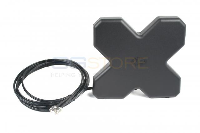
We are currently replacing all the antennas to Mimo-402 and it seems that they didn’t thought very well of the distance between antennas.
I read somewhere that the minimum distance between antennas should be 3m. Is this just a safe assumption or is it possible to install it closer without a great performance drop?
Here is a picture of the mast arrangement and where I would like to install the new antennas.
However, there are upside down antennas and I don’t know really how this would affect. Distance between each other will be maximum 2m.
The minimum distance is generally said to be 50cm but I would recommend 75 to 100cm if possible. If you can get further apart, that’s great, even up to 3-5m.
Installing omnidirectional antennas upside down should not have any adverse affect on the set up and I have done it myself in the past.
The layout of your antennas looks pretty good! What is the distance between the two upside down antennas?
For the connections from the antennas to the router (I’m assuming HD4 with 4x Mimo antennas), you should connect all the main connectors to the top antennas and then the aux connection to the bottom antennas (or the other way around). This gives you multiple paths between your main and aux ports.
Please note we now have a specialised Maritime area of the forum for these posts.
Hello @Jcol7884,
That is a nice looking install.
Antenna distance is based on the frequency wavelengths, it is complicated when you start working with antennas that run multiple frequencies.
That said, we have installations that have to run antennas in a tight density (like up the top of your mast), there is another easy way to put antennas in and have reduced inferring distances. Whatever your antenna length is, make sure that the distance to the next antenna is to not able to be divided by 2, 4, 8 or 16 (dived by 3 is normally OK). Working like this will give you a bit more simplicity in spacing the antennas than just a fixed distance without going to the extremes of the RF mathematics involved.
You may like to ask your local authorised Peplink Partner for a copy of the Antenna Selection Guide available to them from the Partner section of this Forum.
Your local Certified Peplink Partner can help you with a copy of the Antenna Selection Guide for Peplink Partners , this is a detailed guide and is only available to the Peplink Partners so to ensure that you are helped in working through it to get the most suitable antenna solution to your application.
I will take Sam’s advice on the Main and aux antenna location.
About dividing the distance by 3, that wouldn’t be possible. I am guessing this is for the harmonics wave forms?
On a yacht, we try to keep everything as symmetric as possible, so distances are always divided by 2
Thanks for the advice thought, will take it into consideration for new builds.
apologies for jumping into an old thread. I am also on a yacht and I am having very similar difficulties to you and I was wondering how common this is.
I have three MAX-BR1s with two antennas each. Two being MK1s using Laird antennas and one newer LTE-A model with two poynting mimo antennas. Across all three I am getting awful SINR readings, averaging around 3-5db but routinely they are in the negative numbers. I have tried running each device on its own thinking that maybe they were causing interference amongst themselves, but it didn’t make a noticeable difference. Even when in port and the radar and nav equipment isnt running, the SINR tends to be very low, rarely reaching above 10dB.
I’ll leave a couple of screenshots of what I’m getting right now, and for info I’m just off the coast of Sardinia using spannish vodafone SIMs. I’ll show my antenna setup.
With the photo, the outer two antennas are for the older BR1s, with the Main and Aux for each pepwave on separate sides and the spacing between each one is around 70cm.
Hello @marine_engo,
Welcome to the Peplink Community forum.
A few questions:
What is the cable type used from the antenna to the routers?
What is the length of the cable from the antenna to the routers?
How many connectors(joins) are between the antenna and the routers?
Can you log into the router(s) and capture images of the routers recorded signal levels and the frequencies each is using?
You antenna spacing looks fine in the picture supplied.
If you’d like to post what can here for help (ensure to blur/mask all serial numbers), that is fine.
It may be worth reaching out to your Authorised Local Peplink Partner for assistance.
Happy to Help,
Marcus
We are using Ecoflex 15 coax cables. The longest run is about 12 metres, into a small reducer then into the router. The shorter cable is around 8m between antenna and router.
This is the readings from the LTE-A BR1, using the two Poynting antennas:
Hi Tom, welcome to the forum!
Would you be able to try testing with a BR1 connected as close to the antennas as possible e.g. in the deck-head directly below the antennas (preferably to the higher gain Poynting antennas so there is approx 2m coaxial cable run to each antenna)?
On a 12m run at 2600MHz, the attenuation will be about 1.86dB (assuming 15.5 dB per 100m) and on 1800MHz, it would be about 1.51dB. (Please note this does not take into account the smaller jumper cable and connectors.
Regarding interference form other onboard equipment, I would expect that to not be a factor at all in you set up as the cellular antennas are located a decent distance away from the main mast.
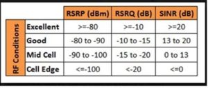
Please refer to this graphic for more info about what each measurement really means
For the limit of one image upload per post, you will be able to upload more than one image in the future once you have been an active & trusted member of the forum, I see you just joined recently. This automatically happens
We are very busy at the moment but I will try that when I get an opportunity. I learnt from this thread that these devices are supposed to be earthed, which hasn’t been done to any of the three. So thats going to be my first point of call to see if that makes much of an improvement.
I also did the cable for the antennas runs along a cable tray consisting of power cables, ethernet cables and the like which is probably another big cause of the problems. I am going to attempt to move the coax so they are at least a little away from the other cables also.